Build your
macropad.
A complete step-by-step guide to assembling your Desk Tech macropad from scratch — from laying out your parts to clicking in your first keycap. Take your time, follow each phase in order, and you'll have a fully working board in under an hour.
Tools required
Tools
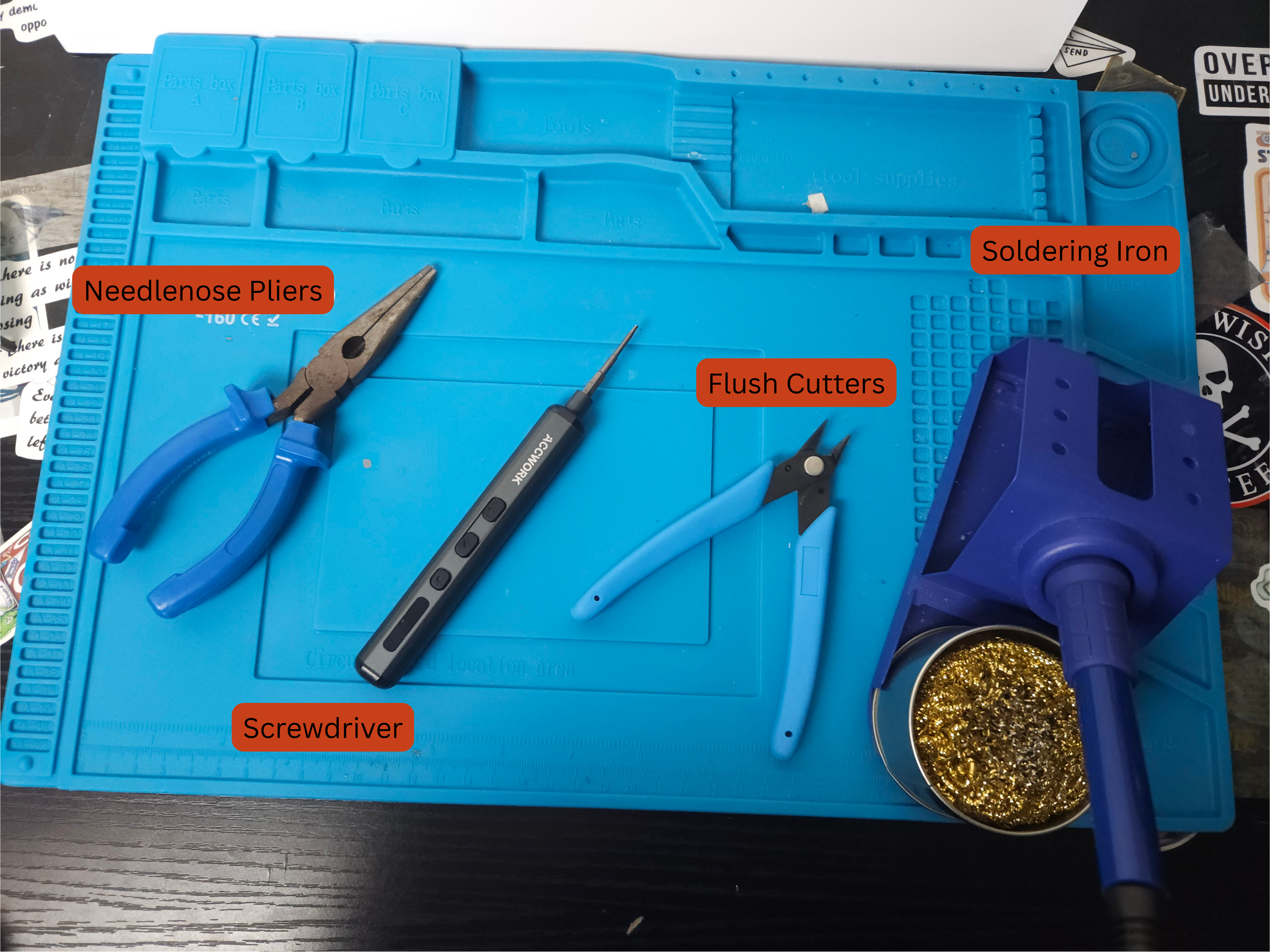
Optional Tools
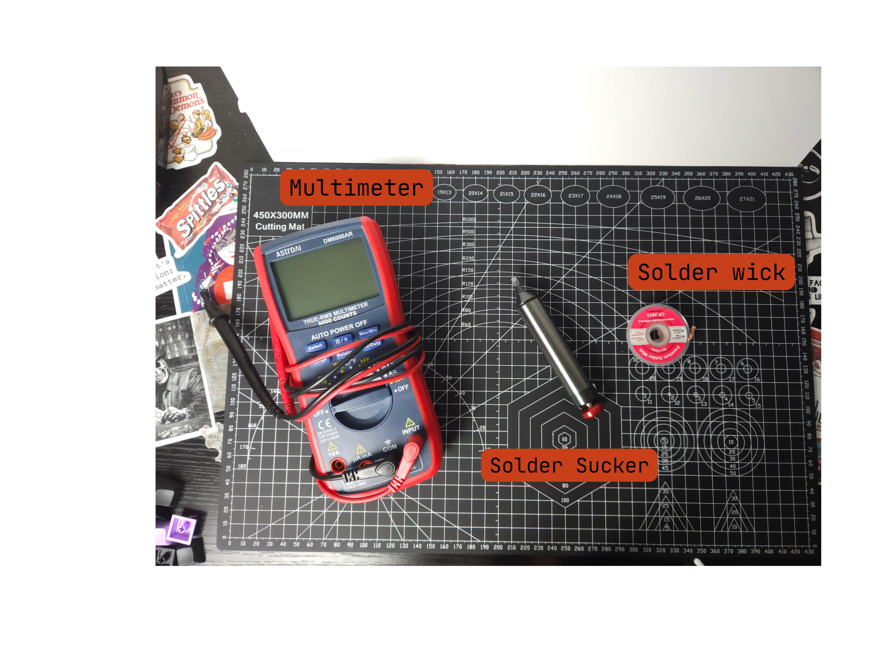
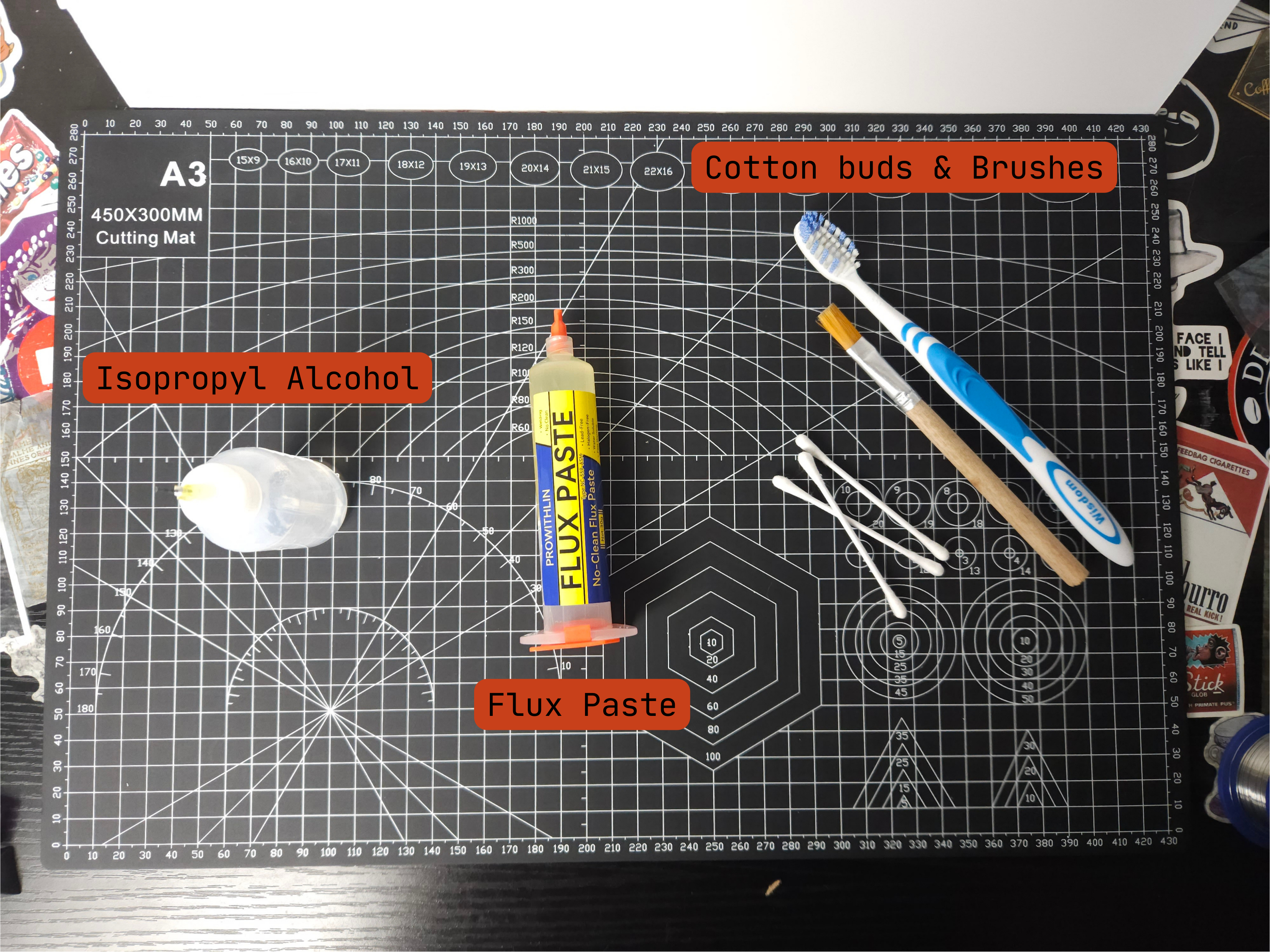
Parts checklist
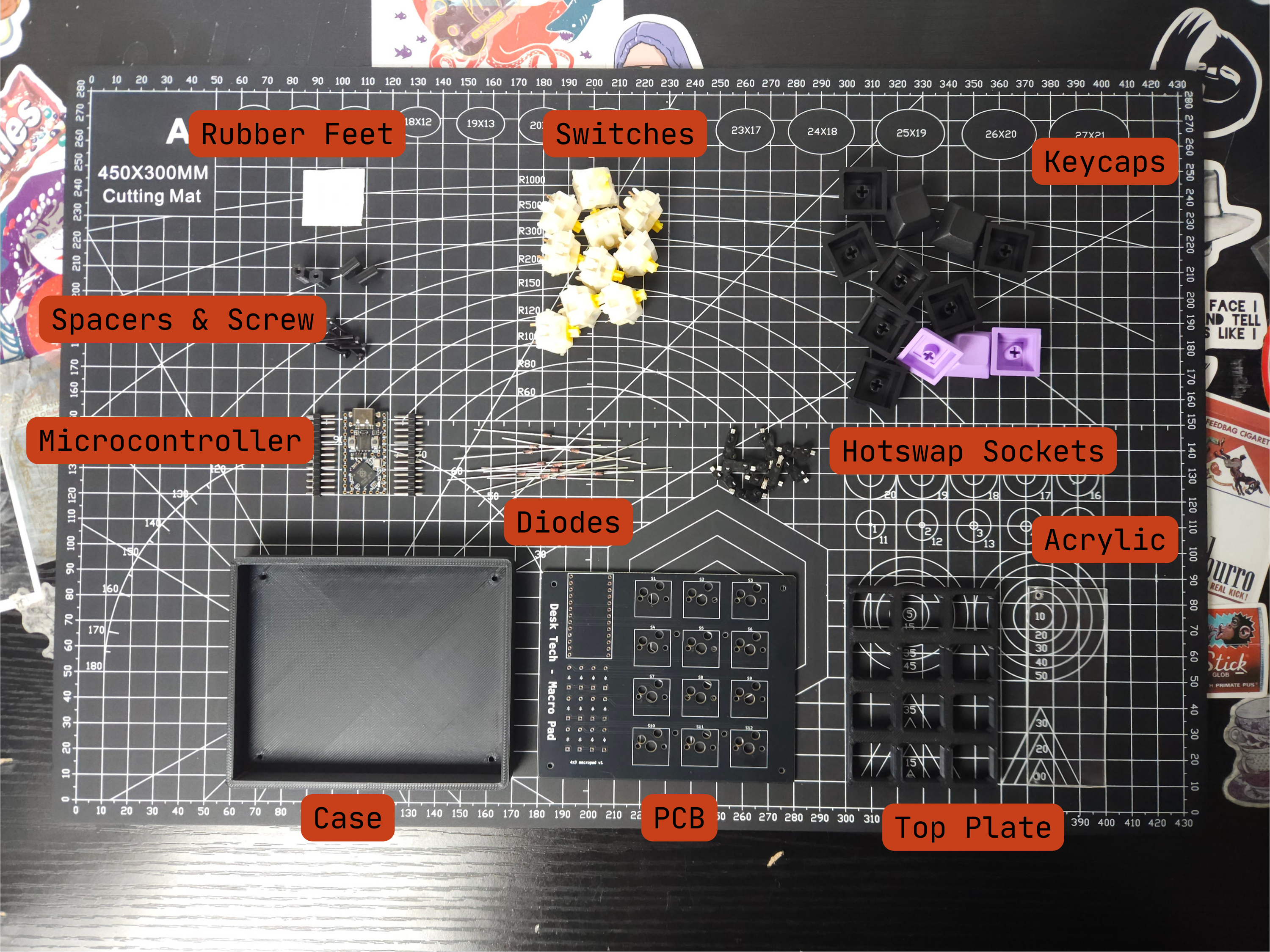
PCB
Microcontroller
Acrylic Screen
Top plate
Diodes
Hotswap Sockets
Bottom case
Milky Gateron Switches
Keycaps
Spacers
M2 screws
Rubber feet
Phase 0 — Printing the case
If you purchased a kit without a case, download the STL files below - all prints are made for a 0.2mm layer height.
Phase 1 — Diodes and Switches
Solder the components onto your PCB before building the case.
Soldering header pins to your board
The first step is to add our header pins to our microcontroller.
To do this grab your microcontroller and the header pins, we are soldering the shorter side of the header pins into the microcontroller.
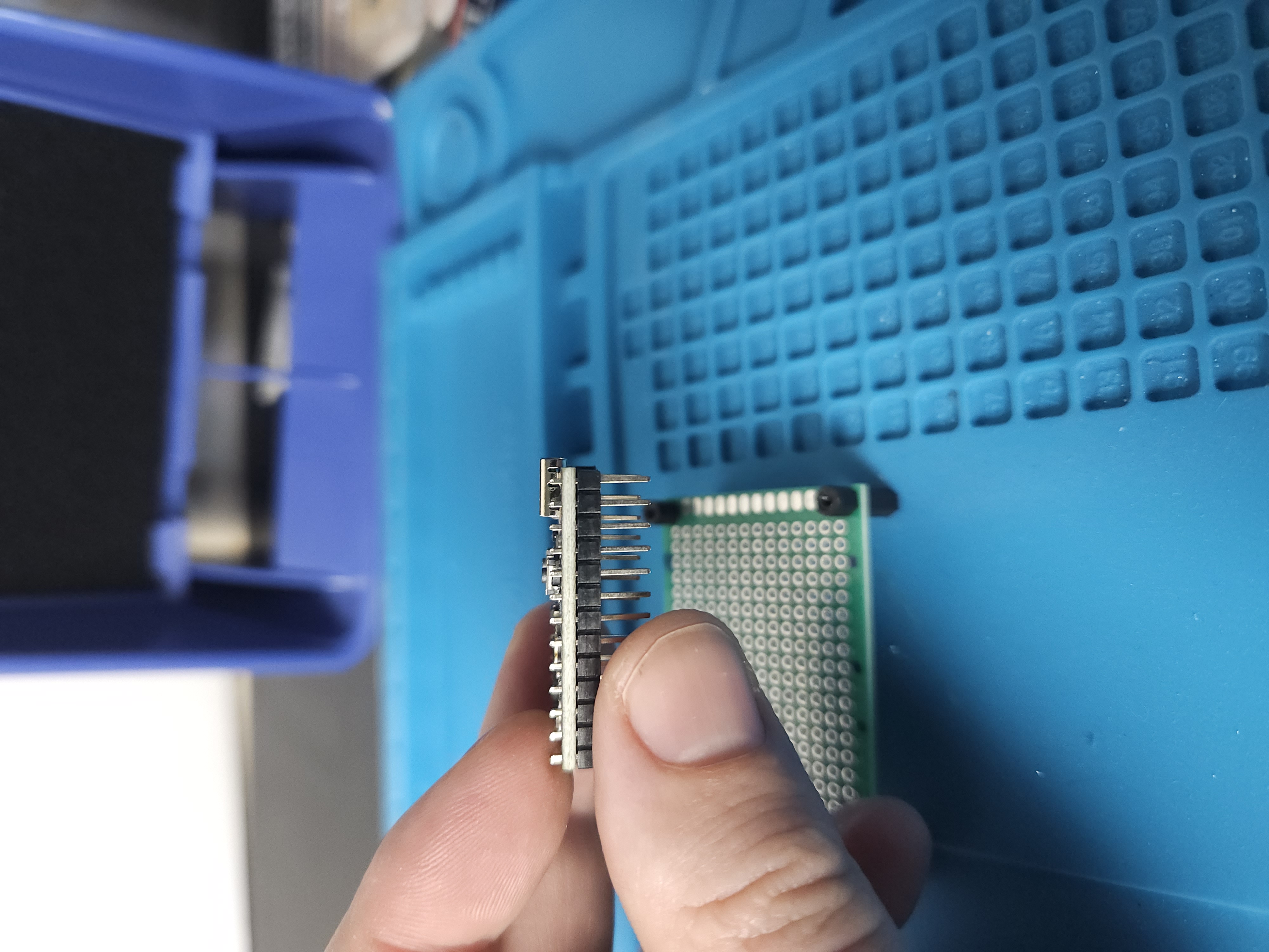
The picture below shows the orientation of the header pins. When soldering it is important to make sure the black plastic on the header pins is flush to the board otherwise one side of the pins will be lower than the other.
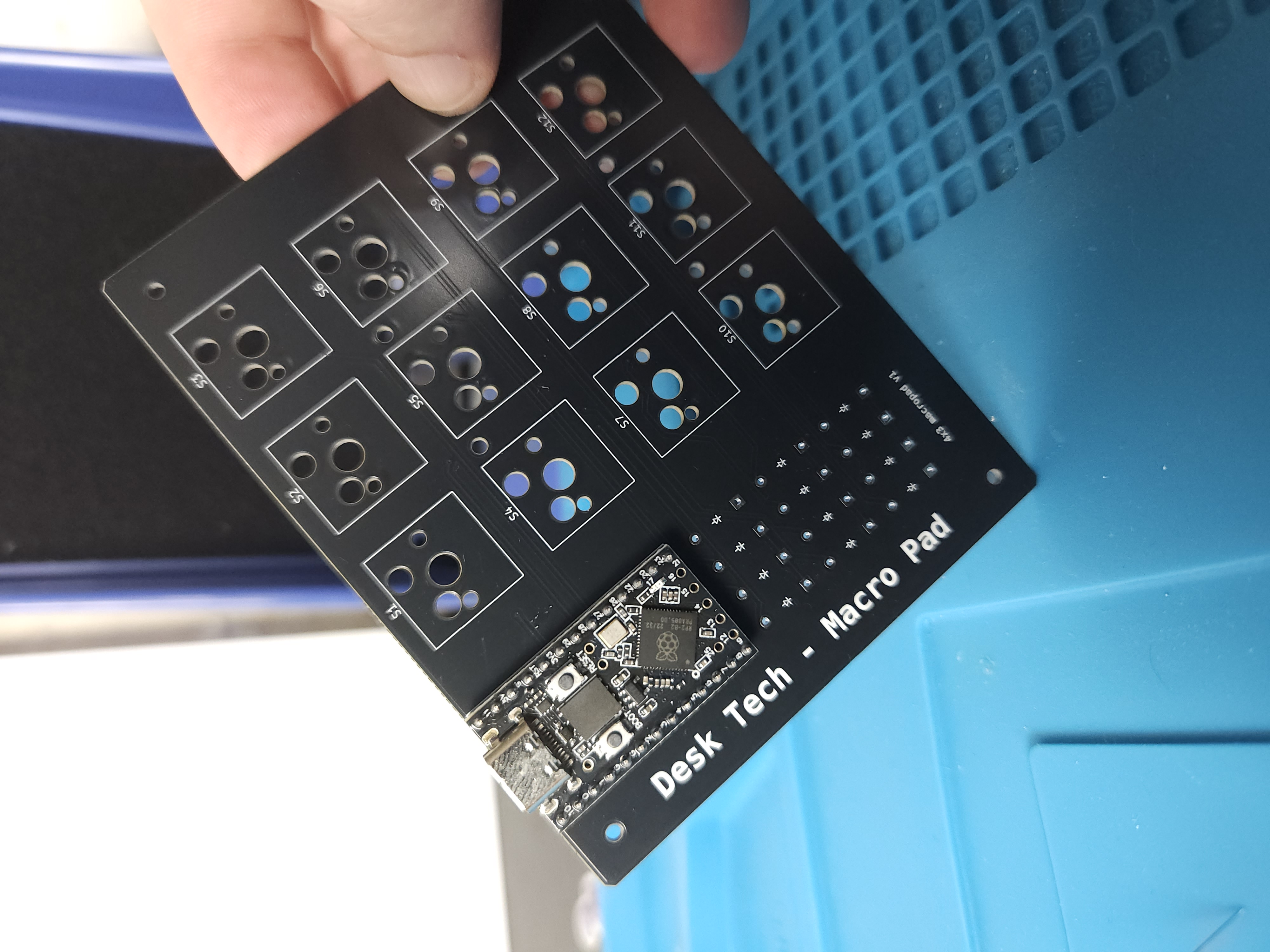
Now to solder the microcontroller to the board! The USB port on the microcontroller should sit at the top of the board.
The pins may need slightly wiggling into place but don't use too much force as you may break the header pins!
Once the board is in place flip the board over and solder the header pins on the back. The finished product should look like the picture below.
Adding the diodes
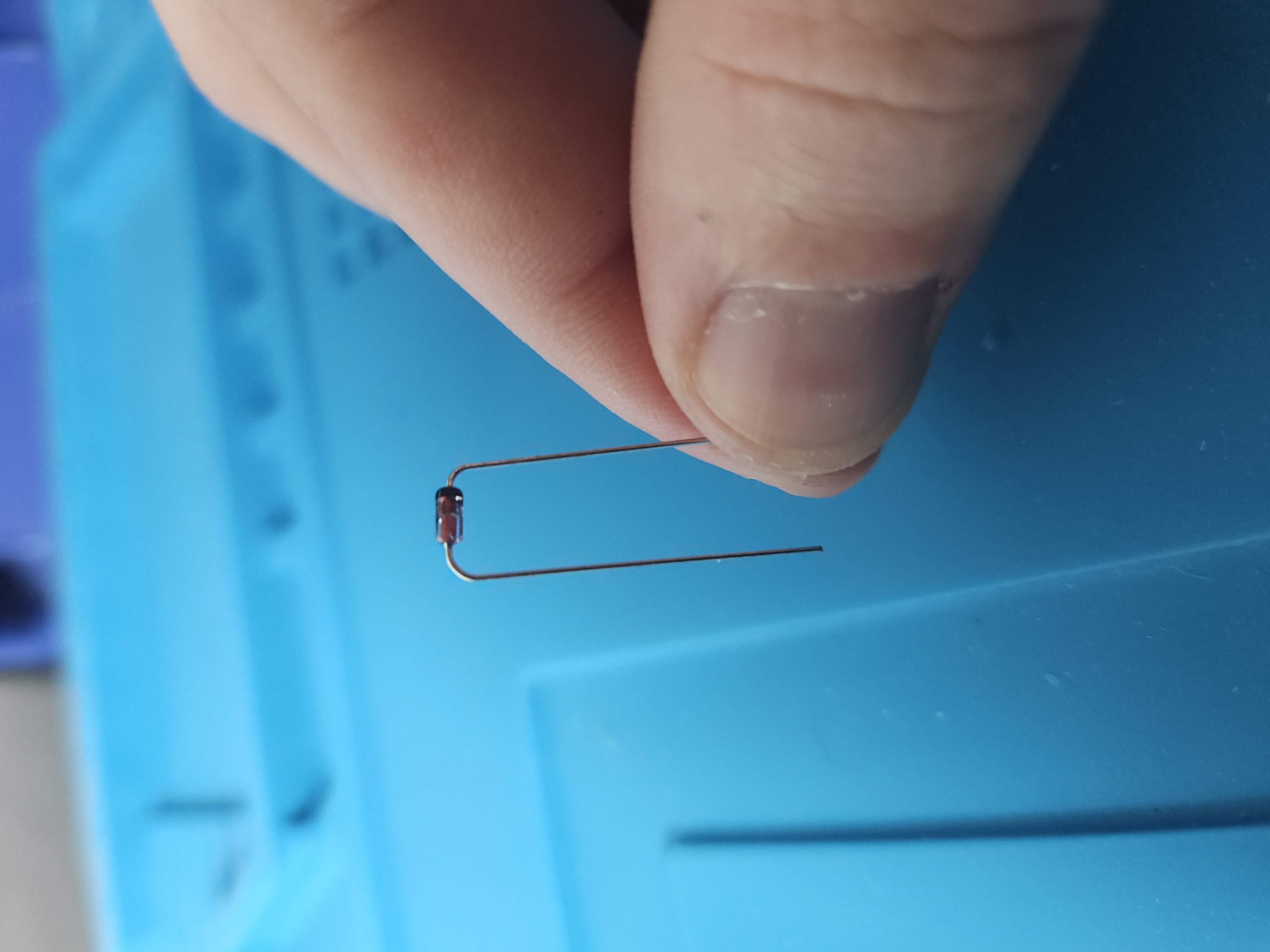
Next up comes the diodes! First we need to bend the diodes — bend each leg to a 90 degree angle until they look like the photo shown. Repeat for all 12 diodes.
The black line on the diode should match the line on the PCB symbols. To begin with, place the first four diodes in the top row.
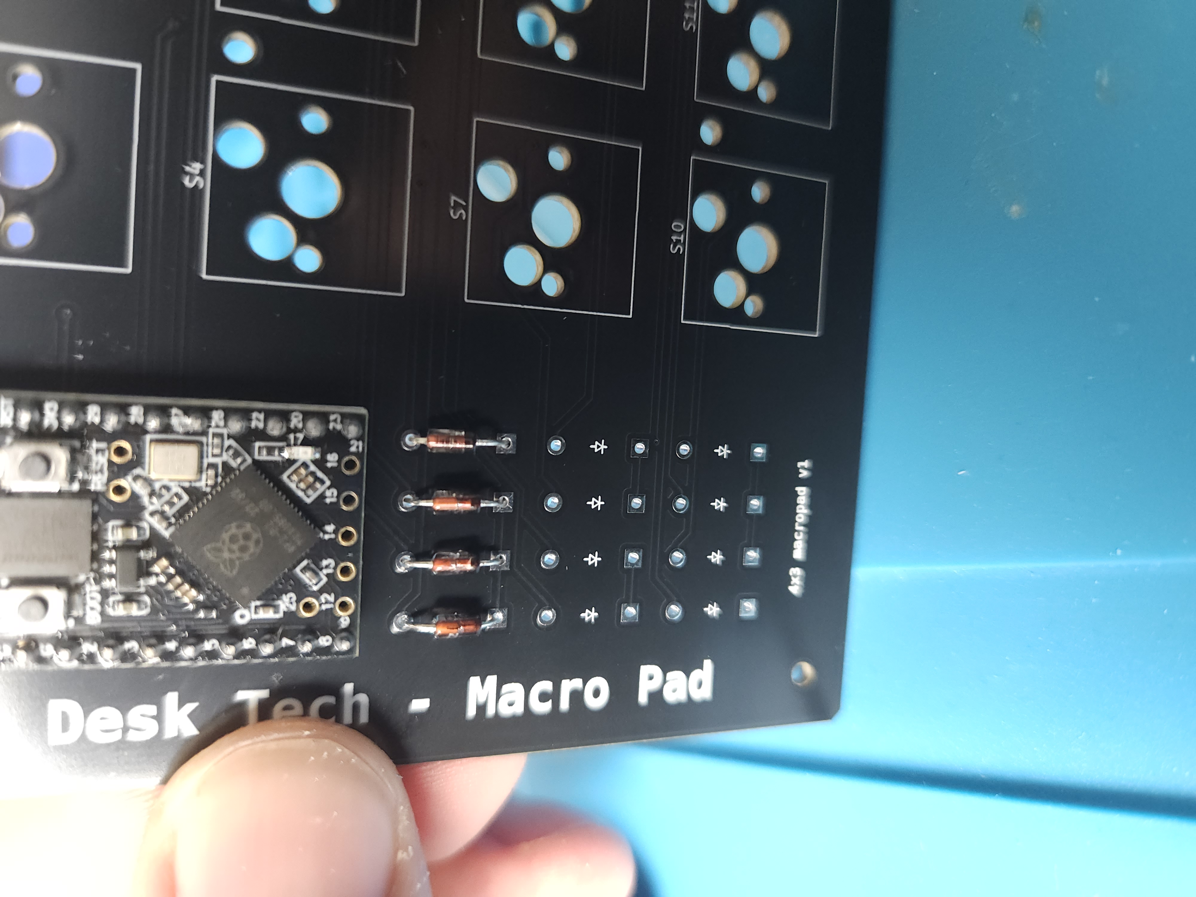
Align the diodes so you are happy with their placement from the front, then flip the board over and bend the legs to keep them in place for soldering.
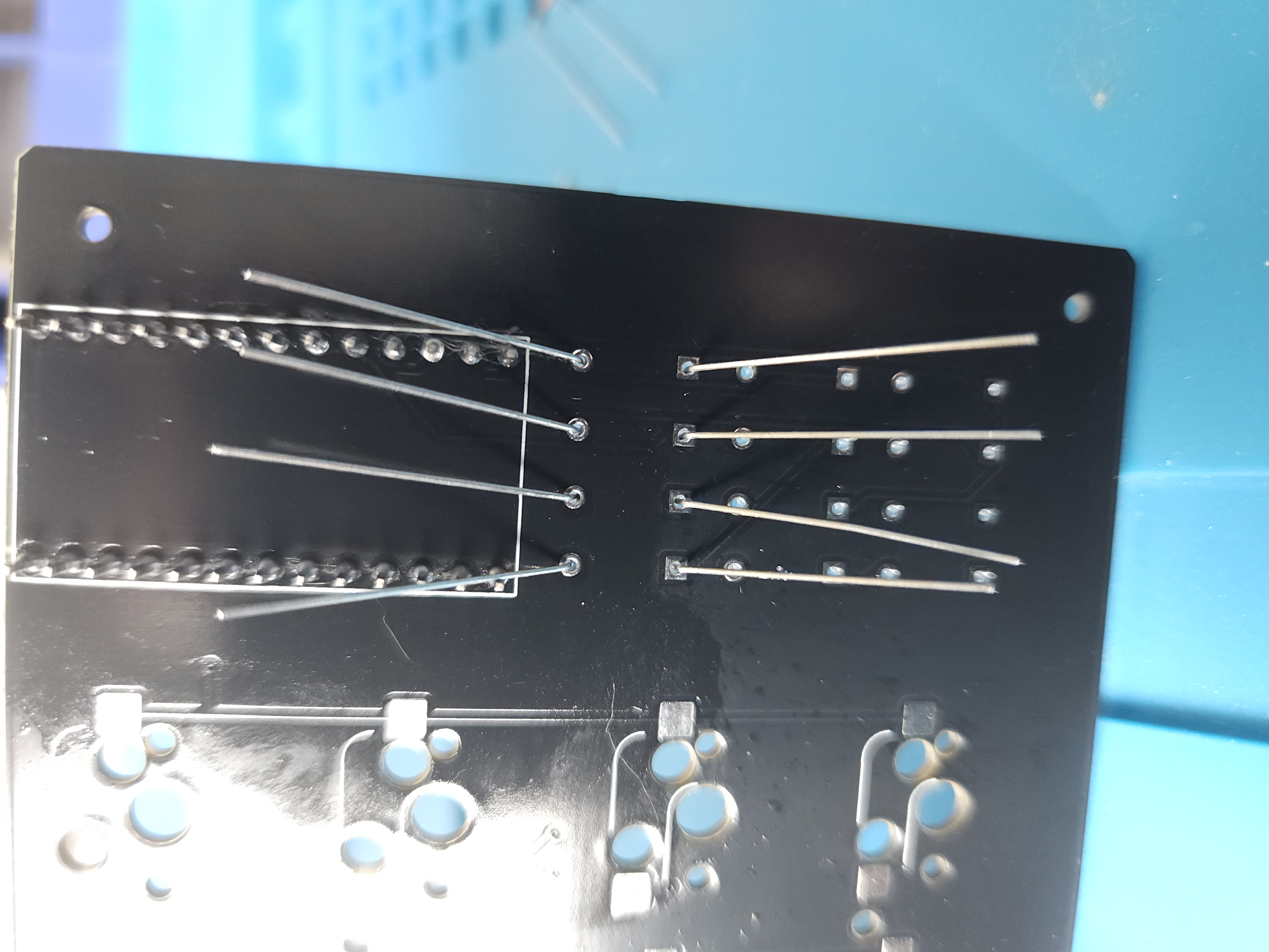
Go through and solder each of the legs. Use the flush cutters to cut down the legs — cut just above where the solder ends.
(Optional) You can now clean off the board with isopropyl alcohol and a cotton bud.
Now repeat for the rest of the rows!
Adding the hotswap sockets
First, with the PCB upside down, tin each pad for the hotswap sockets — this will ensure a strong connection once we place the sockets on. You only need a little solder here otherwise the socket won't sit flush on the board.
Now that each pad is tinned we can place the sockets in. Go through and solder each one. Use a little extra solder here as hotswap sockets provide the physical connection for switches and can occasionally be pushed off, damaging the PCB.
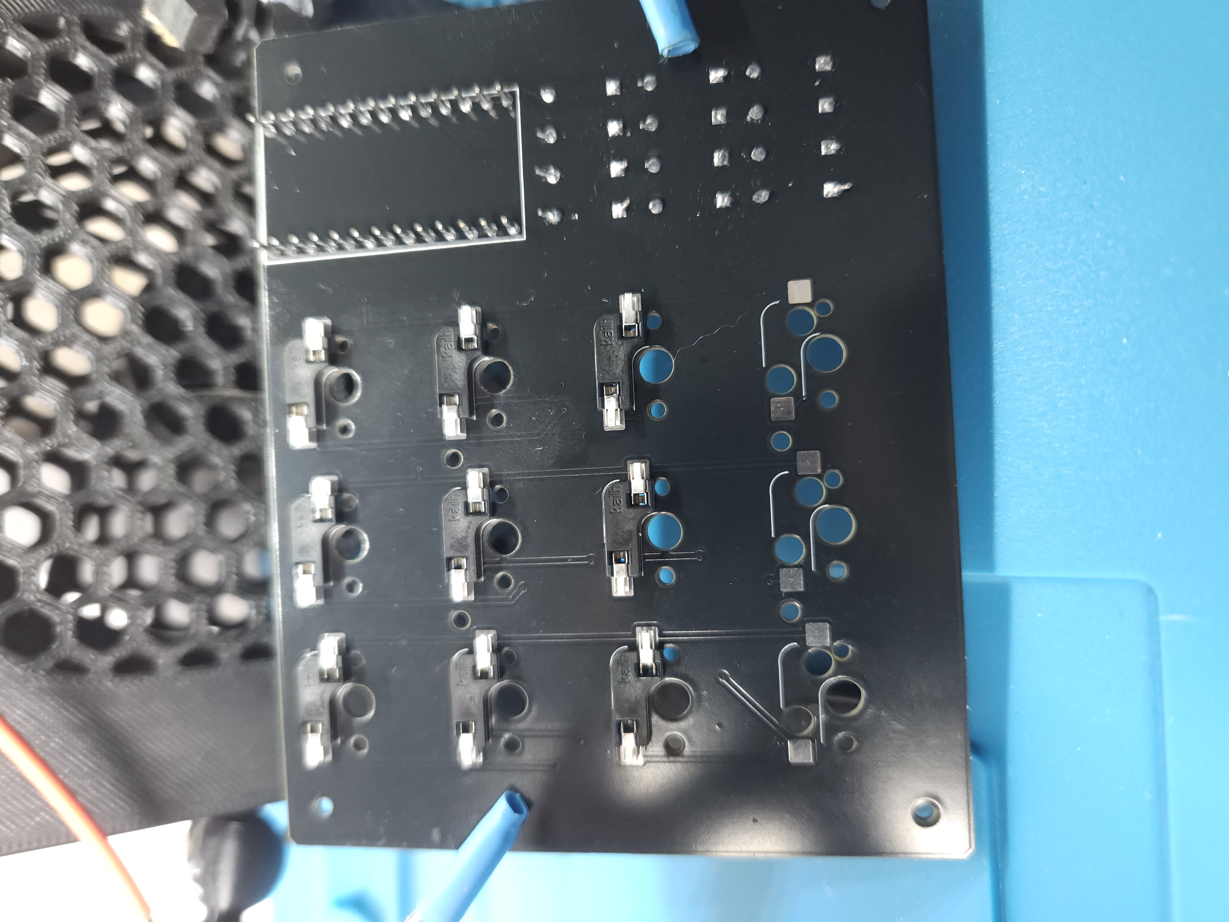
Phase 2 — Building the case
Now we have the PCB all soldered together, let's build the case.
Add the spacers to the bottom plate
Take the bottom plate and add a single spacer to one of the corners, hold the spacer in place and screw in from the bottom of the case using the M2 6mm screws (the shorter ones).
Repeat for each corner until your case looks like the photo below.
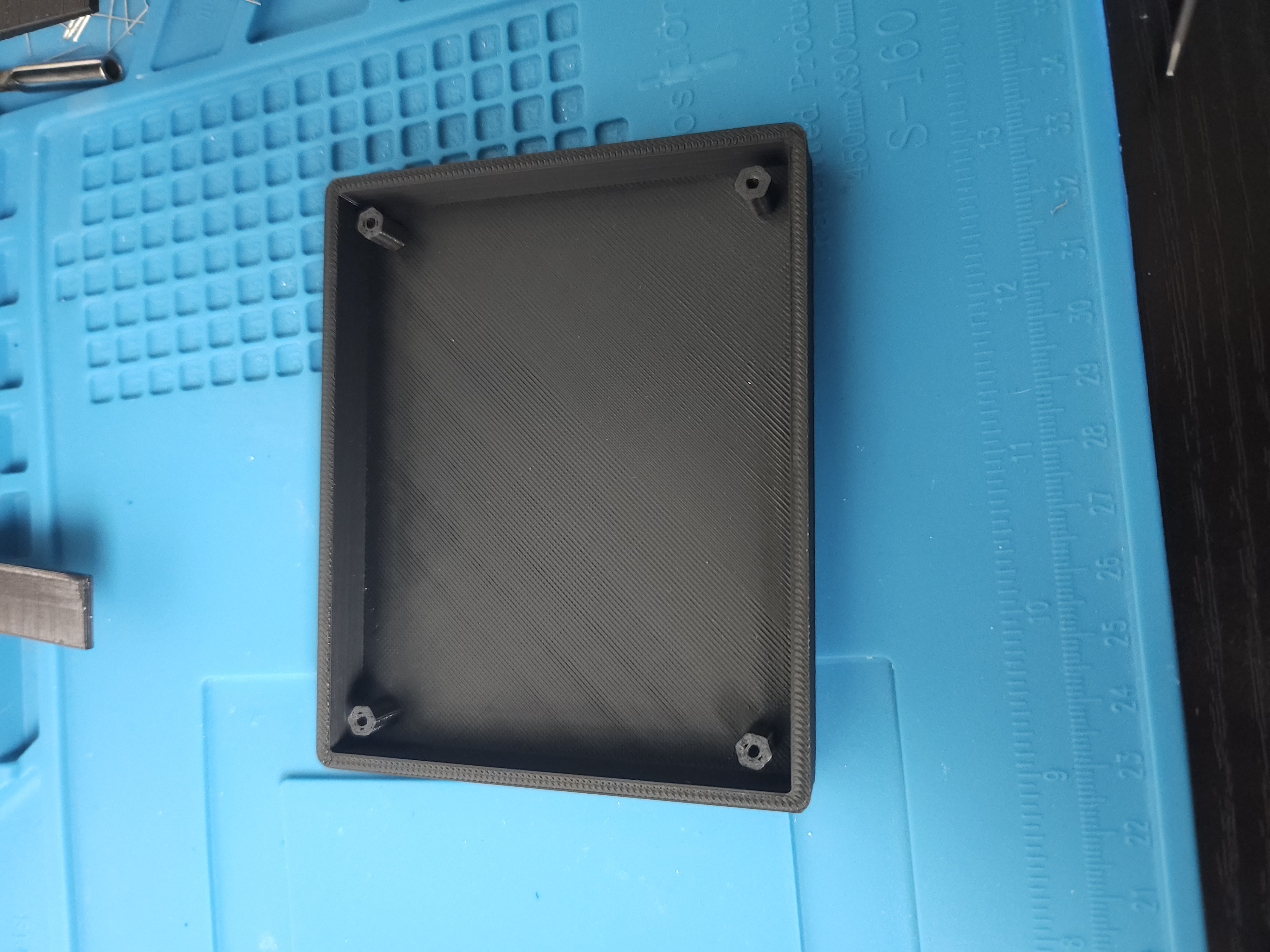
Attaching the top plate & switches
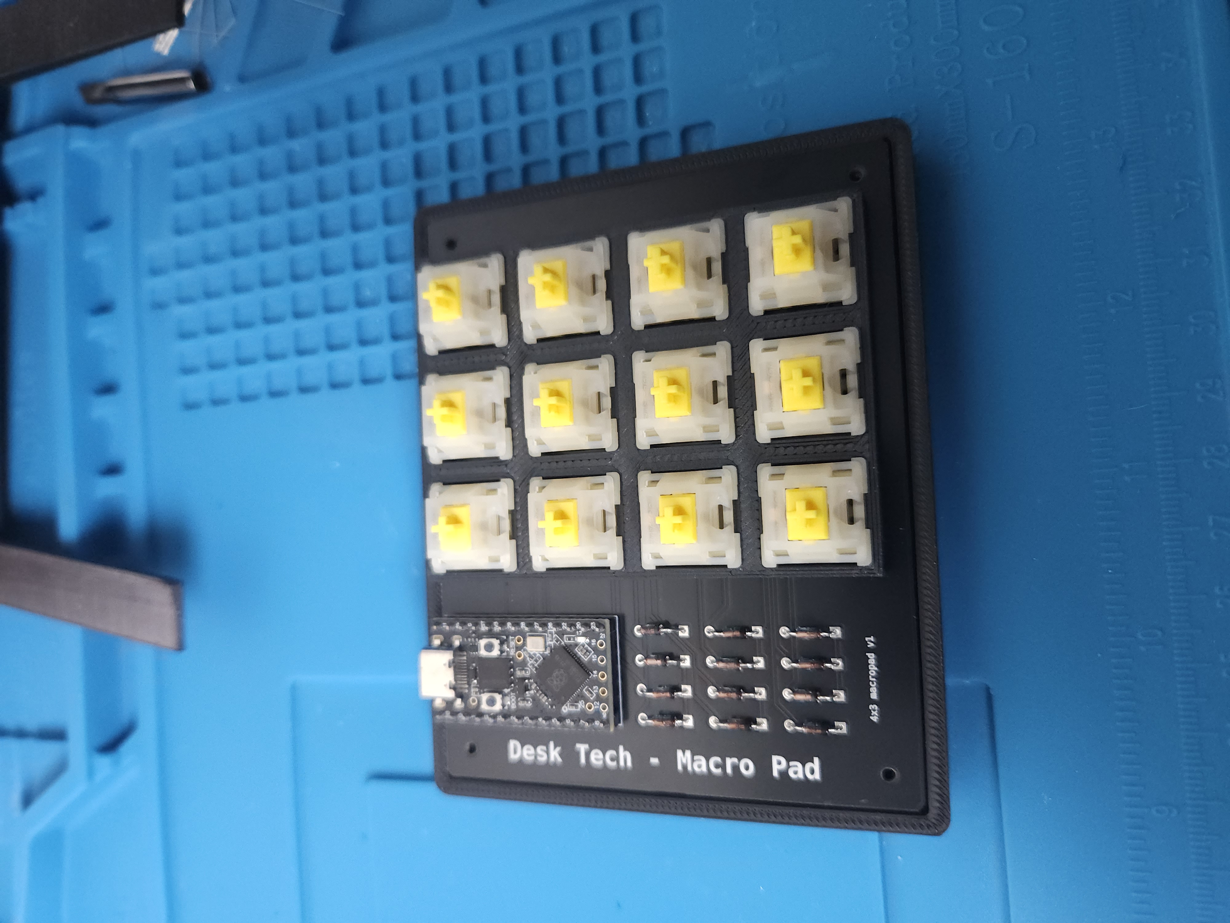
Sit the PCB on top of the spacers in the case. The top plate has small legs which sit in holes on the PCB — locate these and sit the top plate on the PCB like the photo below.
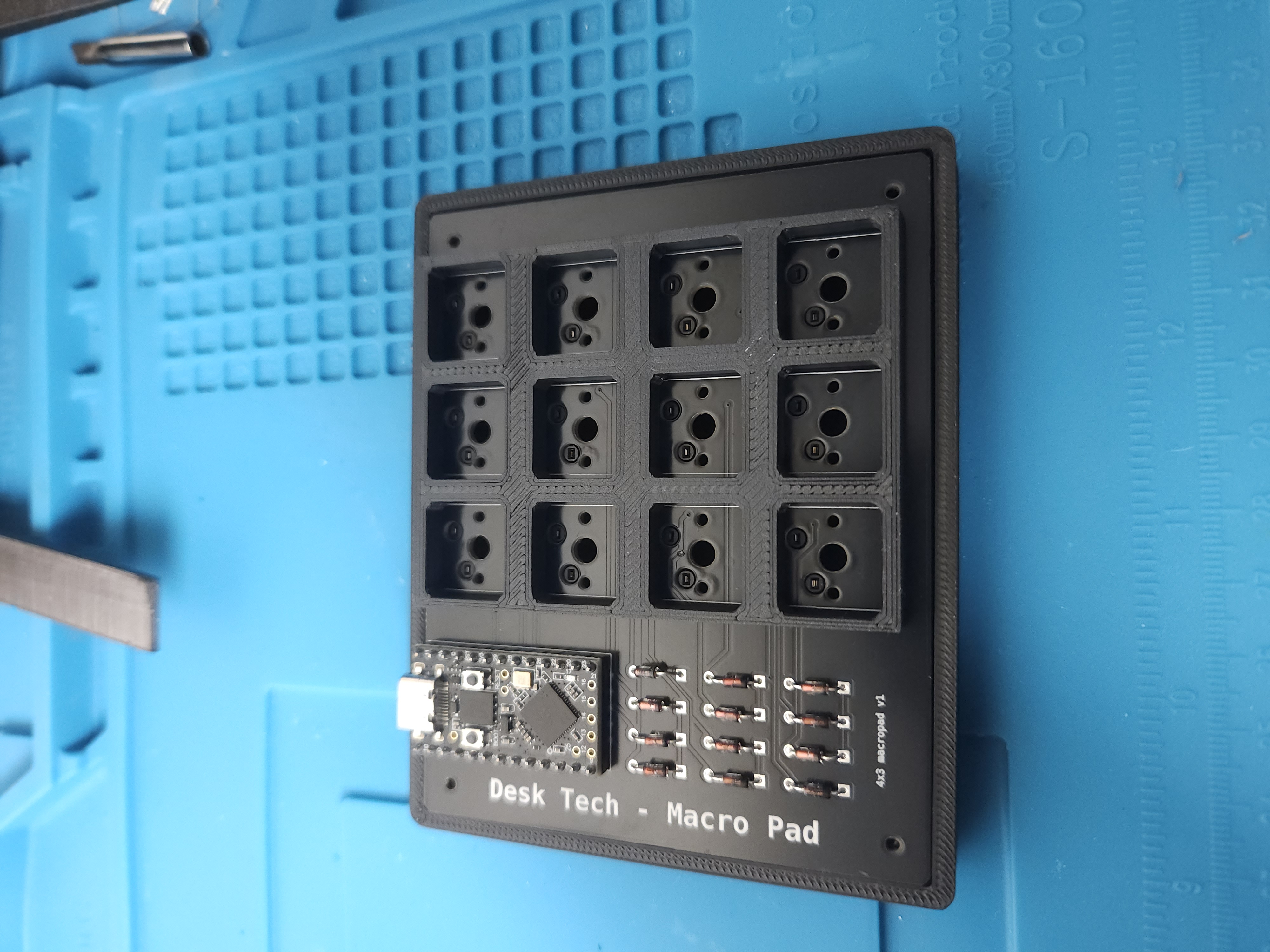
We can now add our switches — these will simply press fit into the top plate. You want the "Gateron" logo to be closer to the top side of the case.
Testing our board
Before we screw our case together let's check that we soldered everything properly.
Plug in a USB Type-C cable to your macropad and to your computer. Open up a text editor and check all keys. If you get a response from every key you can move onto the next step!
If any keys don't respond, check the following in order — hotswap sockets, microcontroller, diodes.
Attaching the board to the case
Now that we have checked our macropad is working we can connect it to the case.
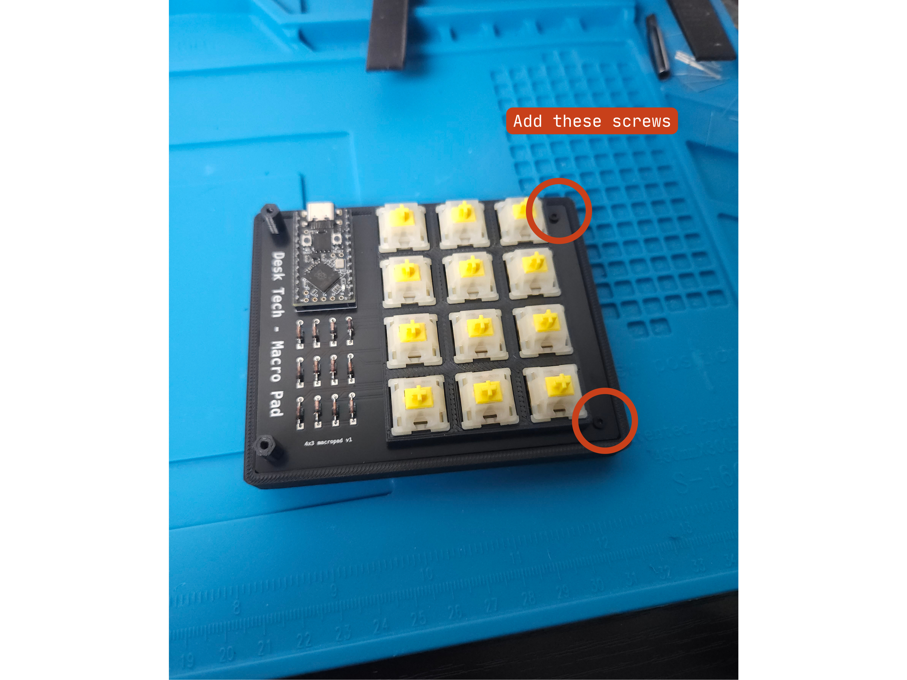
Screw down the right-hand side of the board to the case using 2 × M2 6mm screws.
Add the acrylic screen
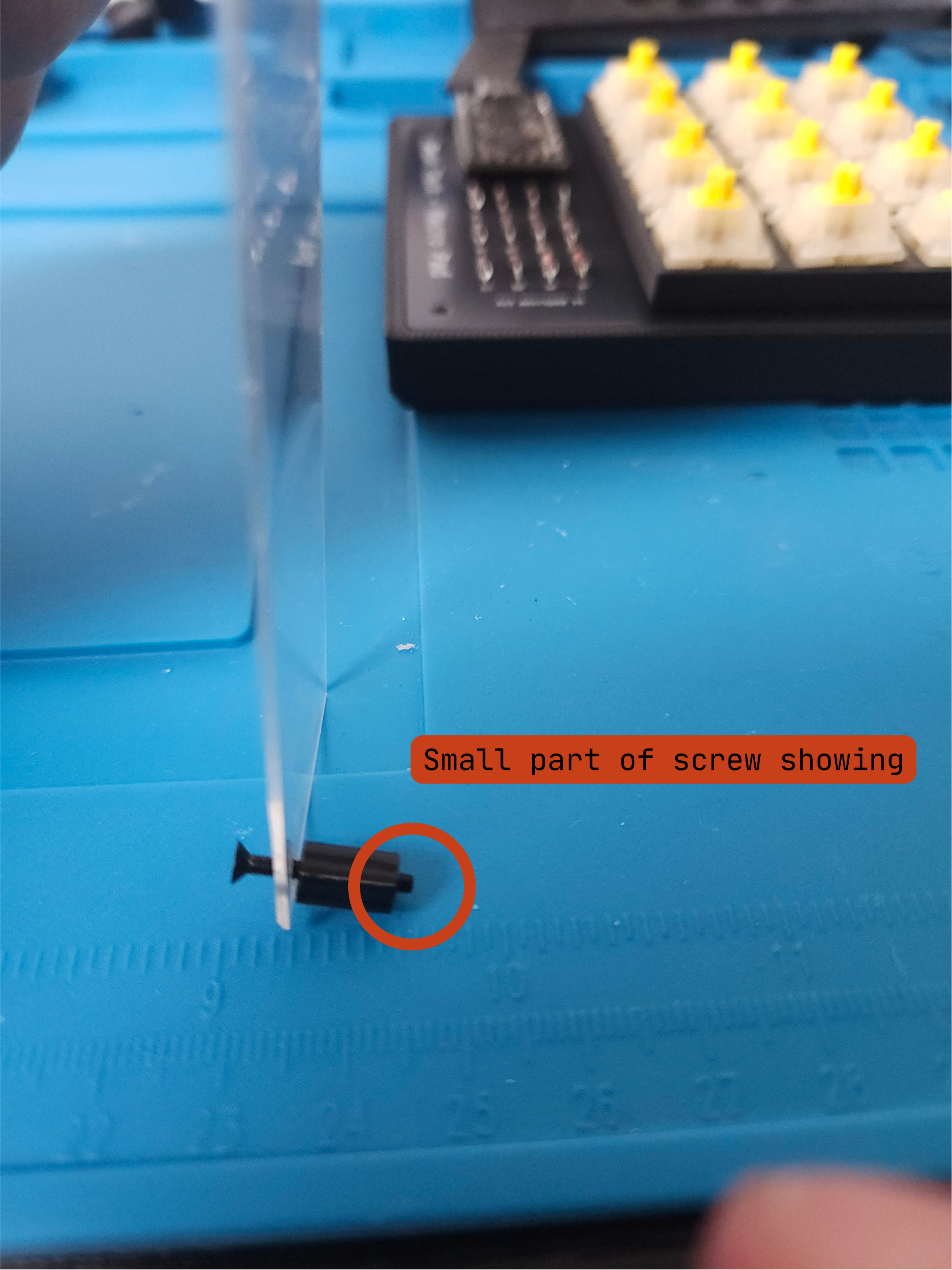
Take two spacers and two 16mm M2 screws and place the screws through the top of the acrylic, screwing into the spacer until a small section of the screw pokes through — this makes it easier to attach to the board.
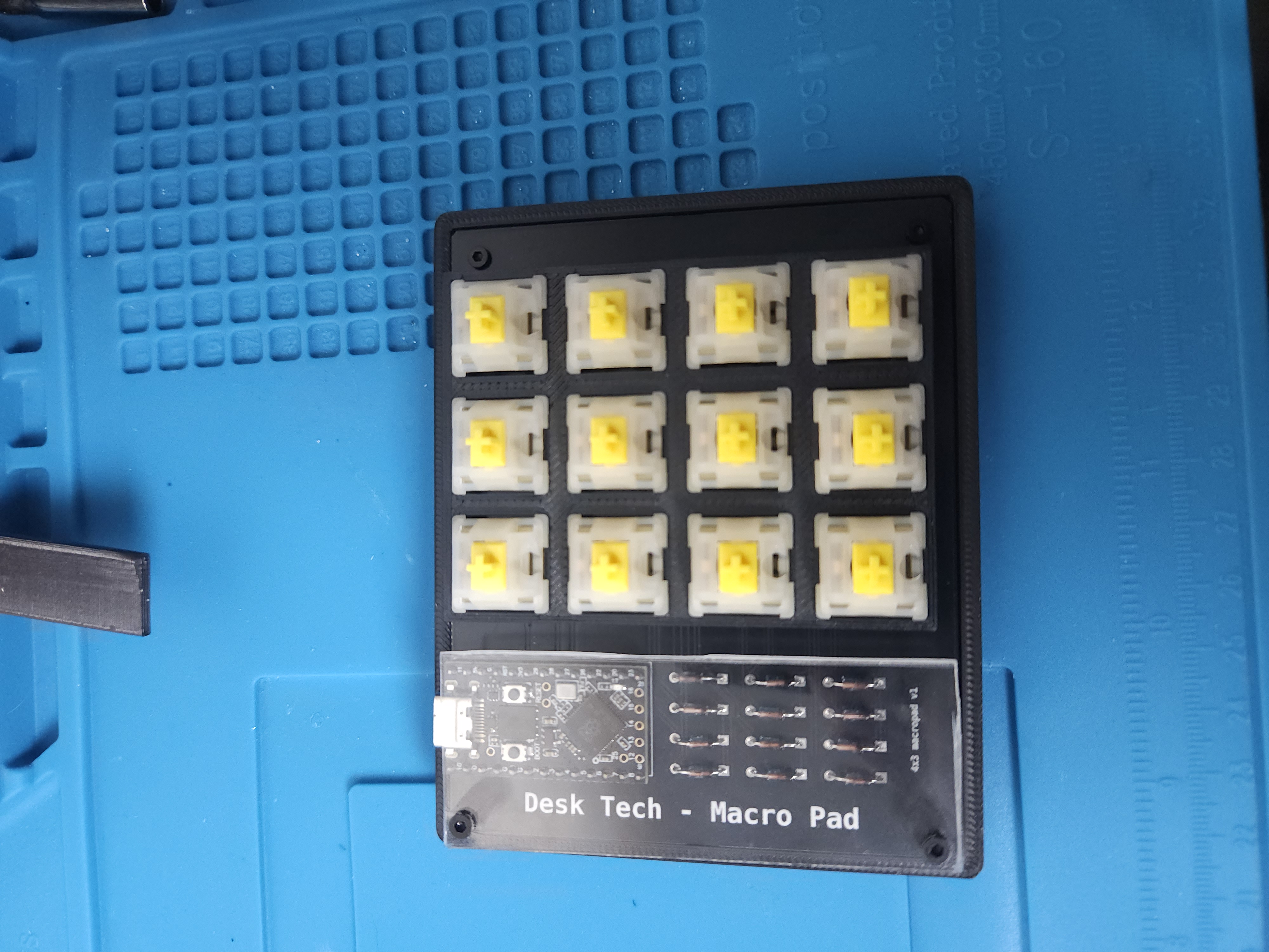
Place the acrylic on top of the PCB, aligning the screws to the holes on the board and screw down into the spacers — careful not to overtighten as this can crack the acrylic.
Adding the keycaps
Now we are ready to attach the keycaps. Each keycap simply pushes into place.
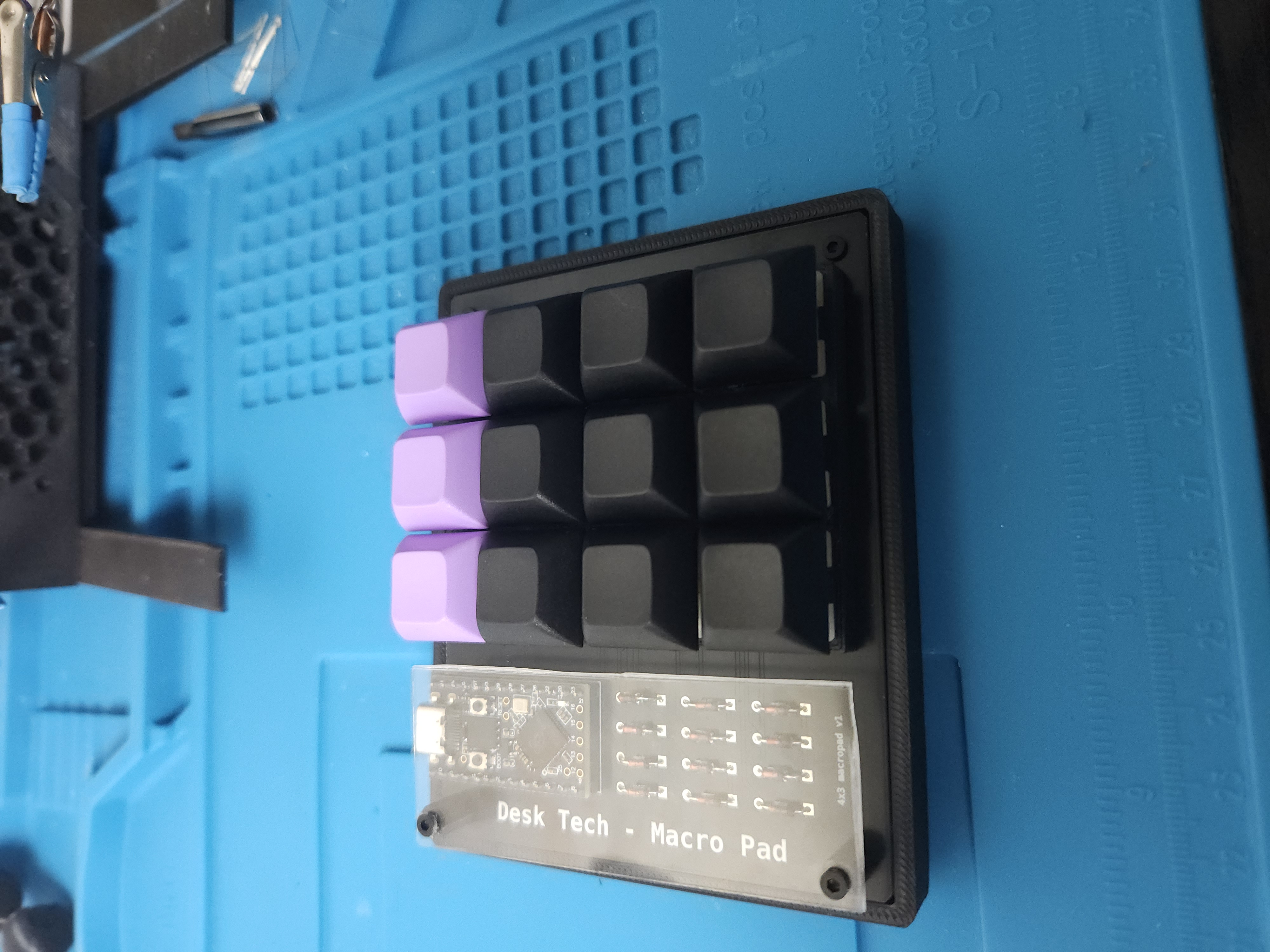
Adding the rubber feet
Flip the case over and add a rubber pad into each corner over the screw holes, then firmly press down to adhere them to the case.
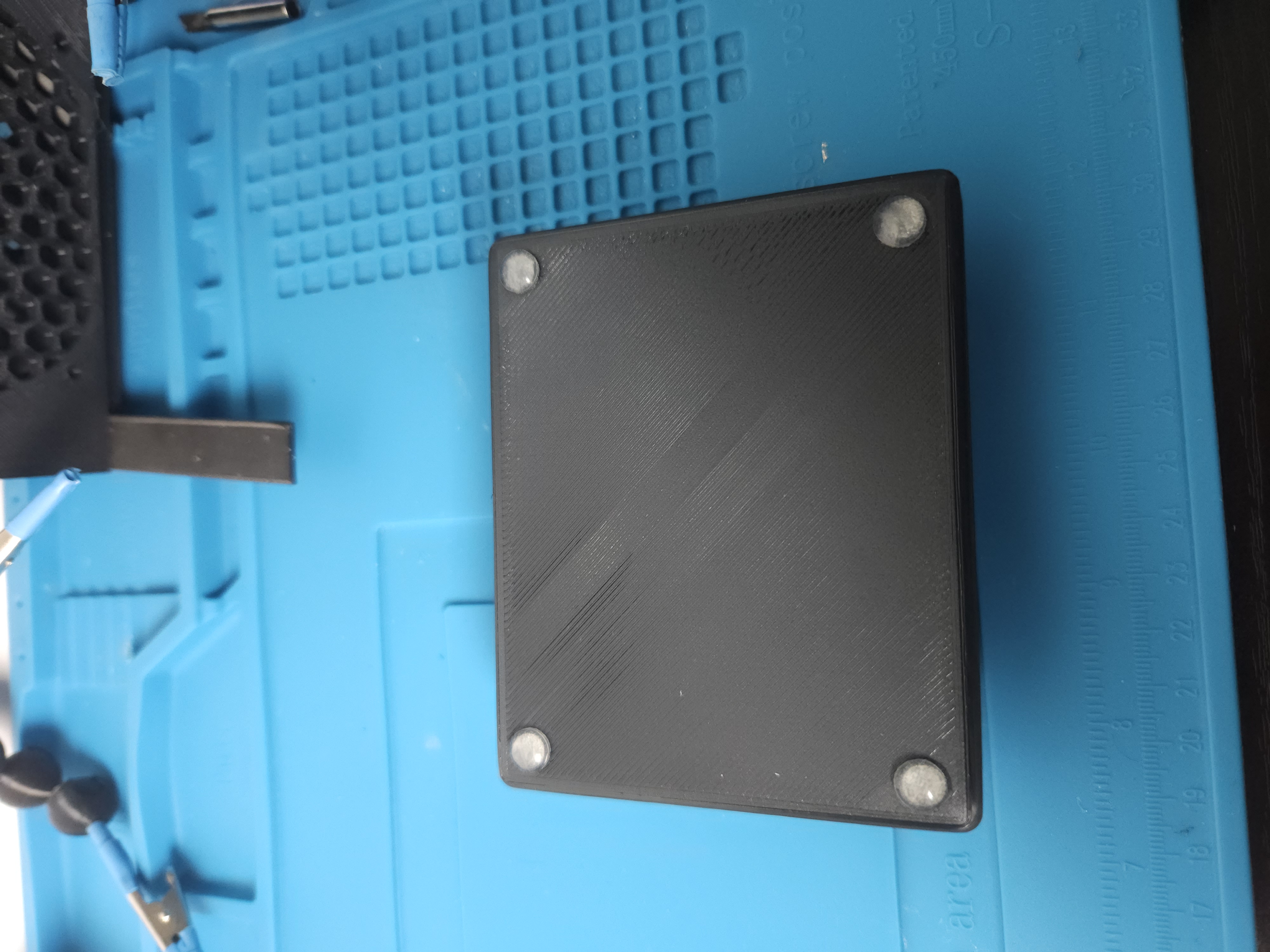
Customising our layout with Via
Now everything is built, let's customise our macropad's functionality!
If you're already confident with Via, you can jump to our quickstart guide which contains all the files you need.
If you aren't confident using Via - here is a quick guide to make your first customisation to your macropad!
Plug your macropad in via USB-C and head to via.app — make sure you're using a supported browser (Chrome, Edge, or Brave).
Click Authorize device — a menu will pop up asking for authorization. Once confirmed, your macropad should appear.
Go to Settings and enable the Show Design tab slider.
Open the Design tab, click Load draft definition, and upload the file.
Your macropad should now appear.
On Linux? You may need to grant your browser permission to access USB devices.
Once your macropad is showing, click any key and assign it whatever functionality you'd like!